
Contactor Wiring Diagram Wiring Harness Diagram
A contactor is an electrically controlled switching device, designed for repeatedly opening and closing a circuit. Contactors tend to be used for higher current-carrying applications than standard relays, which do a similar job with low current switching. What are Contactors Used for?
Wiring Diagram Of Contactor
Single-phase contactor (2 pole contactor) is a widely used instrument in control applications of single phase electrical equipment. With the advantage of being compact, easy to wire, cheaper than three phase contactor with the same capacity.

220 Volt 2 Pole Contactor Wiring
A basic two-pole contactor wiring diagram will typically include a power source, a switch or control relay, and the contactor itself. The power source can be anything from a standard electrical socket to a solar panel, depending on the application.

Single Phase 2 Pole Contactor Wiring Diagram
How to Read a 2 Pole Contactor Wiring Diagram. Reading a two pole contactor wiring diagram can be quite straightforward. The diagram will typically be laid out in a grid format with numbered spots for the various components. The contacts are usually labeled with a letter or a number to identify which is the normally open and which is.

Iec Contactor Wiring Diagram Wiring Digital and Schematic
A two pole contactor wiring diagram shows how two terminals of a two pole contactor interact with each other. The diagram will show which terminal is the 'input' terminal and which one is the 'output' terminal. When viewing the diagram, it will be important to understand that the terminals labeled 'input' and 'output' do not.
120v Wiring Diagram agoinspire
By understanding how to wire a two pole contactor diagram, you'll be able to safely and reliably install the contactor and ensure that it works properly. By following the manufacturer's instructions and using the right size wires, you'll be able to get your contactor up and running in no time. Din Rail 20a 2 Pole Normally Open Ac Contactor For.

Contactors Wiring Diagram
A 2-pole contactor is a device used to switch high-voltage circuits such as motor starters and lighting systems. It basically consists of two separate contacts, both of which are connected to the same power supply. When the circuit is closed, the contacts will make contact and allow current to flow.
How To Wire A 2 Pole Contactor
A two pole contactor wiring diagram is frequently asked for for projects with more than one assembly coming together. These diagrams show the journey of an electrical current, outlining the potential trouble spots and necessary safety methods.

Telemecanique Contactor Wiring Diagram
A two pole contactor wiring diagram is made up of two distinct parts; the contactor itself and the wiring that connects it to other components. The contactor is a device that controls the flow of electricity, either opening or closing the circuit depending on the current state of the system. The wiring diagram is composed of a series.
Two Pole Contactor Wiring Diagram Wiring Diagram and Schematics
Find the wiring diagram you need for 3 or 4 pole contactors, control or overload relays, and motor protector/starters online here at Kent Industries.
single pole contactor wiring diagram ac
What is a Two Pole Contactor Wiring Diagram? A two pole contactor wiring diagram is a schematic representation of the individual wires and terminals that make up the contactor. It shows the path of current flow when the contactor is energized and the sequence of components it interacts with.

How To Wire A 2 Pole Contactor Images and Photos finder
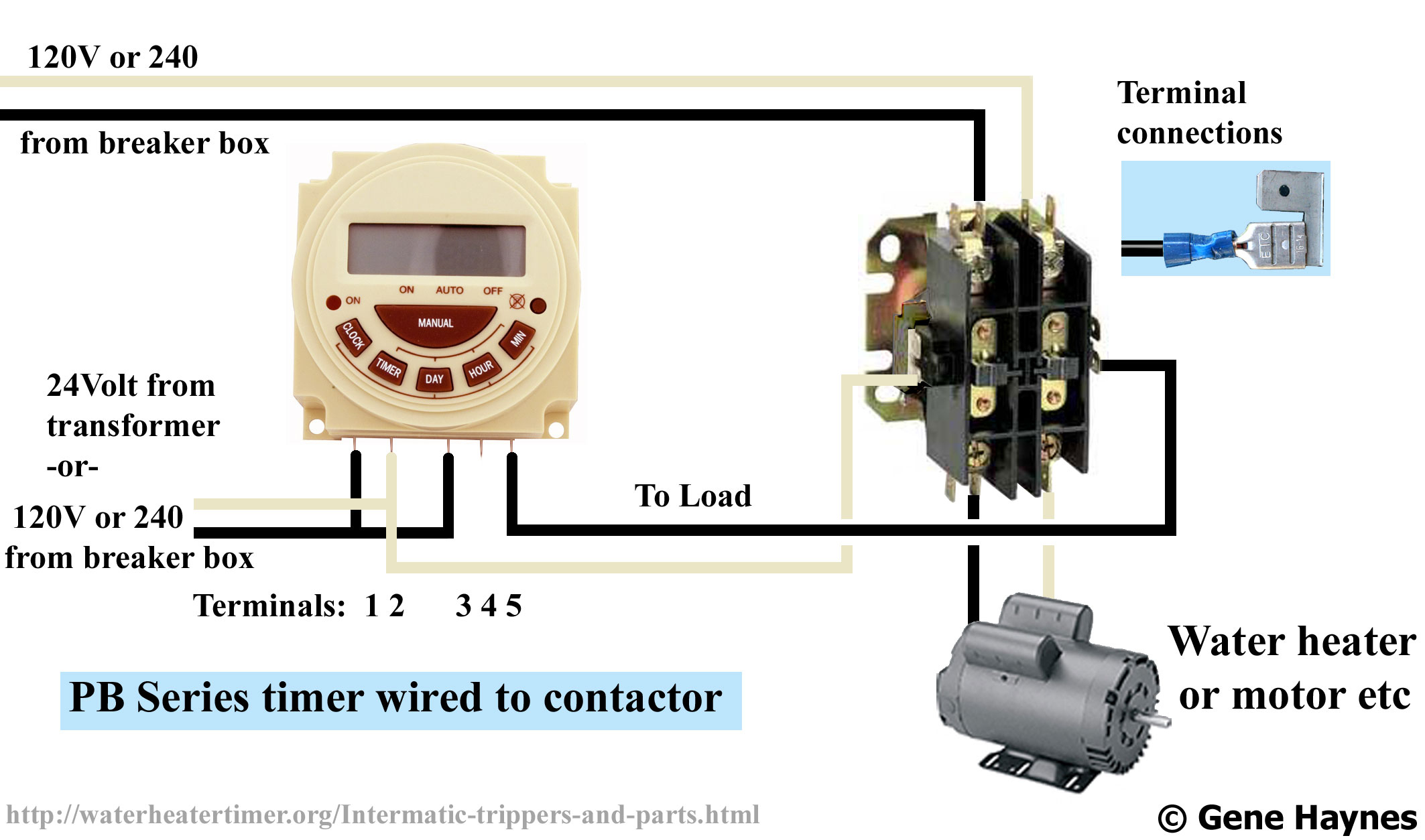
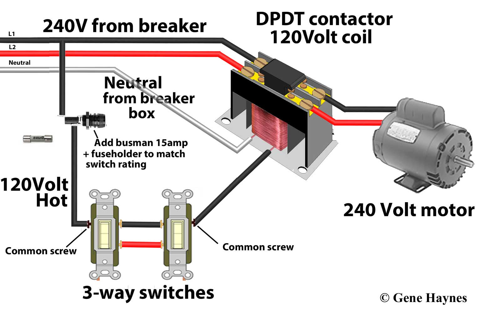
There is nowhere to obtain 120V on your 240V device. There is only Hot L1 and Hot L2 present. To get 120V, there'd need to be a neutral wire there. It's just not there. (and no, you can't bootleg ground). You need a 240V-coil contactor for this. Or, if that's a problem for the float switch, then get 24 volt low voltage from the furnace or.

Single Phase 2 Pole Contactor Wiring Diagram
The wiring diagram 2 pole contactor is composed of two main contacts -- one for line (L) and one for neutral (N). It also has auxiliary contacts for controlling additional circuits. Depending on the type, it can also have a ground (G) connection, which is used to provide additional safety.

Two Pole Contactor Wiring Diagram Wiring Diagram
A 2-pole contactor is an electrical device used to control the flow of electricity in circuits. It has two contacts, one of which is connected to the power supply, and the other is connected to the load.

120 Volt Contactor Wiring Wiring Diagram PDF
These diagrams provide step-by-step instructions for wiring a two pole contactor, which is a type of contactor that has two poles and can be used to control a wide range of electrical loads, including lighting, motors, pumps and more.

2 Pole Contactor Wiring Diagram Dayton
A 2 pole contactor wiring diagram consists of a few simple elements. First, the contactor itself is shown. A contactor is a switch that is activated manually or by a signal from another electrical device. The diagram will also show the electrical load, which is the device that the contactor is controlling. Finally, the diagram will show the.